NEPLAN | PSS/E Import
back to overview
This module is used to reproduce networks that are described in files generated by PSS/E. It can be used for importing files containing information on the network topology and on sequence data to prepare unbalanced network solutions. Load flow and fault analysis calculations and dynamic simulations can be run on the built networks.
PSS/E Import accepts as input files with extension .raw, .seq or .dyr generatred by PSS/E. *.raw files contain the bulk power flow data needed to construct the network and run the power flow calculation. For fault analysis, a *.seq file has to be provided, after the respective *.raw file has been imported to the project. For dynamic analysis, a *dyr file has to be provided respectively.
The module supports the import of networks generated by PSS/E versions 29 to 33.4.
NEPLAN | Phase Swapping / Balance
back to overview
The purpose of this module is to reduce the unbalance in the phases by re-phasing single/two phase loads and lines. Re-phasing is performed in order to:
- Minimize the kW losses
- Minimize kVA unbalance (apparent power)
- Minimize A unbalance (current)
General Characteristics
- Maximum number of swapping can be defined
- Re-phasing works feeder-oriented (multiple feeder selection possible)
- Shows the unbalance and losses before and after re-phasing
- Option for manual re-phasing
Results

NEPLAN | Overhead Line / Cable Parameter Calculation
back to overview
This module allows the calculation of mutual impedances and capacitances in the positive and negative-sequence systems by entering the information on the conductors characteristics and configuration. If the coupling impedances and the line data are known, they can be entered directly in the line-coupling and line data dialogues.
General Characteristics
- Circuit and coupling parameters of the overhead lines are computed from the conductor configuration
- Overhead lines with up to 6 3-phase systems and 3 earth wires can be computed
- Each system can have symmetrical or asymmetrical structure: any phase(s) can be omitted
- Earthing of 3-phase systems is considered
- Unrestricted number of overhead lines can be entered
- Handling of parallel, galvanically connected systems
- Consideration of system characteristics such as segmentation, line-twisting, slacking, etc.
- Parameters and conductor configuration are saved in an SQL database
Line coupling is considered by the Short Circuit Calculation, the Distance Protection Module and for asymmetrical Load Flow.
NEPLAN | Overcurrent Protection (Selectivity Analysis)
back to overview
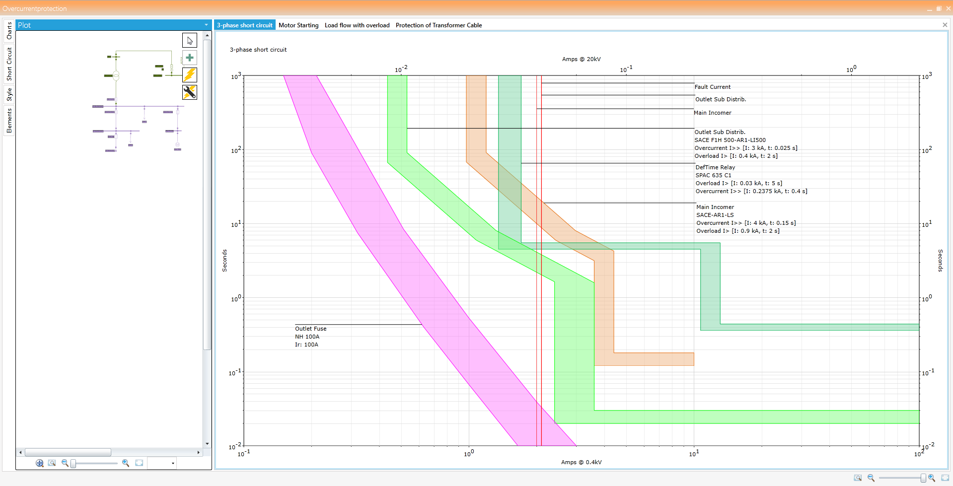
This module is used for the coordination of various over-current protection devices in a given network. The response of the over-current protection devices is visualized in the Time-Current Characteristic (TCC) curve. These TCC curves can be viewed on the selectivity diagram using which the user can adjust the settings of these devices to protect the cable, transformer, etc.
General Characteristics
- All types of protective devices with a current-time characteristic can be entered: fuses, circuit breakers, definite-time and inverse-time over-current relays, electronic relays
- Several protective functions can be assigned to each protective device: non-directional or directional (over-current and earth-fault protection)
- Exact modelling of setting ranges
- Extensive libraries with protective devices from a variety of manufacturers are available and can be extended at will
- Option for entering user-defined characteristics for simulating motor start-ups or thermal capability of cables, damage curves of transformers, etc.
- Characteristic can be shifted using a k-factor (inverse-time relay)
- Entry options for characteristics: point-by-point or formula in conformity with IEC or IEEE/ANSI
- Simulation of fault clearing procedure in meshed networks, involves also distance protection
Selectivity Diagram
- Protection device and current transformers are positioned in the network plan graphically
- Single-line diagram can be viewed in the selectivity diagram
- Automatic generation of selectivity diagrams based on s/c calculation
- Unrestricted number of characteristics can be incorporated in one diagram
- Changing the relay settings directly in the selectivity diagram by moving the curves with mouse or with the help of navigation arrows
- Unrestricted number of diagrams can be processed simultaneously
- Selectivity analysis over more than one voltage level and independently of the network type and size involved
- Two reference voltages for diagrams can be defined by the user
- Individualized colouring of the characteristics
- No limit on number of diagrams and protective numbers for management
- Export of complete diagram to PDF, Word, PNG etc.
- Possible to print the charts from the selectivity diagram
- Axis settings and fonts for the labels can be changed in the diagram
- Short circuit calculation can be done directly from the selectivity diagrams
Transferring Current Values
- Short circuit currents as well as other currents can be incorporated in the selectivity diagram
- Unrestricted number of currents can be transferred into one diagram
Protection Libraries
NEPLAN offers extensive libraries with most used relays-, circuit breaker – and fuse-types. The libraries are constantly updated and extended. They will be handed out for free at the moment of a NEPLAN software purchase or can be downloaded any time from the Internet by users with a valid maintenance contract.
Selectivity Charts
NEPLAN | Operation Modes
back to overview
NEPLAN offers several operation modes:
- Normal application with easy to use graphical user interface
- Calling NEPLAN by a line command (e.g. NEPLAN.exe /batch.dll), which opens NEPLAN, executes the dynamic link library (dll) and optionally closes NEPLAN
- NEPLAN as a listener to a TCP/IP bus, where commands are recognized and performed
- Calling a dynamic link library (dll) with any NEPLAN calculation engine
- Calling NEPLAN or calculation engines through web service
These operation modes are used for integrating NEPLAN with Geographical Information Systems (GIS), SCADA, DMS, EMS, SmartGrid application and others or for defining batch procedures.
The communication between NEPLAN and an external system is bi-directional. Thus, results from the calculation can be further processed.
NEPLAN | Optimal Capacitor Placement
back to overview
The purpose of this module is to identify key locations in the radial primary feeders of a distribution network, where the placement of shunt capacitors minimizes the MW losses.
General Characteristics
- Option for purely technical evaluation
- Option for additional financial data for economic evaluation
- In presence of capacitors libraries, the module selects the most economic sizes
Results
- The bus of the primary feeder, where a shunt capacitor would be located
- The MVAR size of the capacitor
- The additional reduction in MW losses (in %)
NEPLAN | Optimal Network Restoration Strategy
back to overview
This module is designed to study the impact of single forced (e.g. fault on a line) or planned outages on the electrical distribution system. It finds the optimal switching plan to restore electrical power to customers. It may be used as an off-line application to pre-define strategies in case of outages or as an on-line application to help the network operator find quickly the correct strategy after a fault has occurred.
The following objective functions are implemented:
- Minimize network losses
- Minimize the number of overloaded elements
- Minimize the average loadings of the elements
- Maximize the average voltage
Restoration Stages
- Four stages in the restoration strategy will be evaluated and may be stored in a fault history database:
- Occurrence of the fault
- Isolation of the fault. NEPLAN shows the unsupplied customers
- Re-supply of customers which are affected by the fault. NEPLAN shows which customer are re-supplied again
- Normalization of the network after the repair of the fault
- All stages of the selected optimal restoration plan with the new switch positions will be graphically displayed on the single line diagram
DMS On-Line Application
- Results with the new switch positions of all re-supply stages, including all objective functions are displayed as spreadsheet tables or can be accessed as text file for further evaluation (e.g. in DMS applications)
- All dialogues and restoration algorithms are available through a C/C++ API, the NPL – NEPLAN Programming Library. With NPL NEPLAN data and functions can be accessed with a user written C/C++ program. This allows building up customized restoration strategies for network operators
NEPLAN | Optimal Separation Points
back to overview
Optimal Separation Point module eliminates all network meshes by changing the network topology. From the possible topology states the procedure selects one topology that minimizes network losses, considering all activated constraints and without creating isolated sub-systems.
General Characteristics
- User selects which elements are allowed to be switched off
- Option for prevention of overloaded elements
- Option for prevention of limit violations of node voltages
- User-defined activation and deactivation of constraints used for the optimization
NEPLAN | Network Reduction
back to overview
This module is designed to reduce the size of a network model by replacing sets of buses and their connected elements (lines, transformers, etc.) with a smaller but exact, numerically equivalent network. For a properly chosen set of buses, this equivalent network will have fewer buses and branches than the original, yet still provide the correct response to faults or load flow calculations in the unreduced portion.
The network can be reduced for
- symmetrical or asymmetrical short circuit calculations according to IEC60909, ANSI/IEEE or superposition method and
- load flow calculation
The reduced network gives the same short circuit or load flow results as the original network. Giving the nodes to be reduced, the program determines the boundary nodes automatically.
Given any network for short circuit or load flow calculation and the nodes to be reduced, boundary nodes are automatically determined. Functions to select a complete network area to be reduced are available.
The reduced network will be represented by shunt and series equivalents, as well as equivalent infeeds. Depending on the type of network reduction, shunt and series equivalents consist of data for the positive, negative and zero system. For load flow network reduction boundary injections and boundary generators are calculated.
NEPLAN | Network Modelling
back to overview
NEPLAN is handling any type of electrical networks for transmission, distribution and industrial/generation.
Network types:
- Meshed or radial 1-phase, 2-phase, 3-phase with separate representation of neutral and/or ground
- Meshed or radial DC systems
- Combination of AC and DC networks with AC/DC and/or DC/AC converter
- Grounded, impedance grounded, resonance-grounded and isolated
Voltage levels:
- Ultra-high voltage to low voltage
- All voltage levels are handled in one calculation run
Grouping of network components
- Area/subarea, zones/subzones, feeder, substation, element groups
- Partial networks, isolated networks, grounded networks
- Owner
- Tie-lines or -components
Passive network components
- Overhead lines with tower geometry and calculated mutual coupling
- Any cable with parameter calculation
- 2-, 3- and 4- winding and autotransformer
- Special asymmetrical transformers (single, two-phase or three-phase configuration)State-of-the art Phase shifting transformers (4-quadrant)
- State-of-the art on-load tapchanger with asymmetrical voltage step and impedance correction
- Voltage regulator and thyristor-based regulator (single, two-phase or three-phase configuration)
- Filters and RLC components
- Earthing transformers and earthing systems for common earthing of components
- User-defined models
Switches
- Load switch, disconnect switch, busbar coupler (single phase, 3-phase configurations)
- LV-, MV-, HV-circuit breaker (single phase, 3-phase configurations)
- Grounding switch and surge arrester
- Remote controlled switches
- Automatic reduction of switches during calculation
Substations
- Any substation configuration with/without bay definition
- User defined switch bay configuration
- Supports hierarchical structure
- Substation templates could be used
- Definition of grounding system
Renewables and Energy storage
- Small and large hydro power plant
- Small and large wind power with detail representation
- Photovoltaic
- Biogas
- Fly wheel for AC/DC machines
- Compressed air storage
DC-components
- HVDC classic with DC-lines (2-port or 3-port configuration)
- Voltage source converter, HVDC-light (2-port or 3-port configuration) and PWM
- DC-reactor and DC-shunt
- DC-batteries, DC-Fuel cells and DC voltage source
- DC photovoltaic panel
- DC-motor and DC-load
Compensation components
- Line compensation
- Block-wise shunt compensation in fix, discrete or continuous control mode
- Static Var compensation and STATCOM
- Series-compensation with over voltage protection
Generators
- Synchronous machines with state-of-the-art models for steady state and dynamic behaviour for nuclear power
plant, hydro power plant, gas power plant, combined cycle power plant, coal-fired power plant
- Direct drive synchronous machine with permanent magnet
- Double fed asynchronous machines as one port or two port model
- Disperse generation
- External Grid (voltage source)
- User-defined models
Motors
- Asynchronous machines with all kind of start-up devices
- Synchronous with all kind of start-up devices
- Automatic motor parameter identification out of input values in function of slip
- Converter fed drive
- User-defined models
Loads
- Motor, constant current and constant power load or mixed
- Composite load for LV-consumers
- LV-loads assigned to lines, e.g. cables
- Frequency dependent loads for HV
- synthetic load profiles (day, season) and measurements
- load forecast
Controllers
- Generators, motors, transformers, compensation, HVDC, VSC or any other component could be controlled. e.g.
Automatic Voltage regulators, Turbines, Governors, PSS
- Secondary control for frequency or balancing control
- Controllers are built with help of function blocks or simulation language (MatLab)
- Pre-defined controllers are available
Protection
- Over current relay with i/t characteristic, supports all standards IEC, BS, ANSI/IEEE
- LV- and MV-circuit breaker, fuses, recloser
- More than 3500 protection models available
- Distance protection with any R/X-characteristic
- Voltage, frequency and power swing relay
- Pole slip relay
- Differential relay
- User-defined modelling of any protection device with function blocks