NEPLAN | Loadflow Time Simulation
back to overview
The module Load Flow Time Simulation uses measured time series as well as synthetic load or generation profiles. Based on the normal load flow calculation, time ranges from minutes to years can be simulated. The result is again time dependent quantities, which are evaluated using statistical methods. In case synthtic load or generation profiles are used, the loads and generations are scaled according to the profiles defined for a Day, a Weak or Season and for a Long Term behaviour (see Scaling Types section).
Evaluations
- Time-value curves
- Violated limits are reported (maximum values and time percentage)
- Minimum, maximum and average values
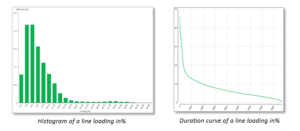
- Histograms for voltages and element loadings
- Duration curves for any variable type
- Storage of minima and maxima as operating conditions
Main Features
- Statistical values visible in the single line diagram
- All results can be displayed in charts
- Results tables
- Option for parallel calculation
- Topology changes definable
Video:
- Time simulation with synthetic profiles could be found here.
- Time simulation with field measurements could be found here.
- Time simulation with load allocation could be found here.
NEPLAN | Cable Sizing
back to overview
This module is used for the selection of the type and cross-sectional area of a cable as well as the protection device for an assumed passive or motor load and a given infeed. The cable type can be selected either from the predefined cable library within NEPLAN or from user-defined cable libraries depending on various international standards such as VDE, IEC, NEC, etc. The basic principle underlying cable sizing calculations remains the same for all these standards. However, it is important to consider the geographical conditions and then select an appropriate standard. The module can also be used for the inspection of already installed cables.
General Characteristics
- Automatic selection of protection device rating and setting. Device is taken from NEPLAN protection library
- Sizing of one cable or any number of cables together (distributed radial network)
- Maximum length of selected cable type and section for which the criteria is still fulfilled
Criteria of dimensioning
- Service current of consumer, influence current rating of cable
- Protection of cable against overload
- Tolerable voltage drop and voltage limits
- Protection against hazardous voltage (people protection), influence switch off in tolerable time
- Protection of cable against short-term overheating
Results
Proper dimensioning of cables ensures that they can:
- Operate continuously under normal operating load conditions without getting overloaded
- Operate continuously during motor-starting operation if applicable
- Switch-off within defined time for minimum short-circuit current in a network
- Withstand maximum short-circuit current to avoid thermal damage of the cable
- Provide downstream loads with proper operating voltage by making sure there is no excessive voltage drop in the cables
Apart from the cable cross-section area and the maximum cable length, the module provides with further results, including voltage drop condition for normal and motor start operation, criteria for overload and short-circuit protection, tripping times etc.
NEPLAN | Network Reduction
back to overview
This module is designed to reduce the size of a network model by replacing sets of buses and their connected elements (lines, transformers, etc.) with a smaller but exact, numerically equivalent network. For a properly chosen set of buses, this equivalent network will have fewer buses and branches than the original, yet still provide the correct response to short circuit or load flow calculations in the unreduced portion. The network can be reduced for
- symmetrical or asymmetrical short circuit calculations according to IEC60909, ANSI/IEEE or superposition method and
- load flow calculation
The reduced network gives the same short circuit or load flow results as the original network. Giving the nodes to be reduced, the program determines the boundary nodes automatically. The module supports WARD, Extended Ward and REI-DIMO equivalents. There are several options to handle the non-linear elements, like PV-Generators, during the reduction process.
The reduced network will be created as a variant of the original network. In this case both networks could be easily compared.
NEPLAN | Overhead Line / Cable Parameter Calculation
back to overview
This module allows the calculation of mutual impedances and capacitances in the positive and negative-sequence systems by entering the information on the conductors characteristics and configuration. If the coupling impedances and the line data are known, they can be entered directly in the line-coupling and line data dialogues.
General Characteristics
- Circuit and coupling parameters of the overhead lines are computed from the conductor configuration
- Overhead lines with up to 6 3-phase systems and 3 earth wires can be computed
- Each system can have symmetrical or asymmetrical structure: any phase(s) can be omitted
- Earthing of 3-phase systems is considered
- Unrestricted number of overhead lines can be entered
- Handling of parallel, galvanically connected systems
- Consideration of system characteristics such as segmentation, line-twisting, slacking, etc.
- Parameters and conductor configuration are saved in an SQL database
Line coupling is considered by the Short Circuit Calculation, the Distance Protection Module and for asymmetrical Load Flow.
NEPLAN | Arc Flash Calculation
back to overview
Arc Flash module in NEPLAN offers the user to analyze and assess the high risk of arc flash in power system. Arc Flash calculation is completely integrated and based on NEPLAN short circuit and overcurrent protection modules. It calculates the incident energy for reduced and unreduced arcing currents in function of the working distance and automatically determines the Arcing Fault Clearing Time. It also determines individual arcing current contributions.
General Characteristics
- Arc Flash Standards:
‒ IEEE 1584-2018
‒ IEEE 1584-2013
‒ NFPA 70E-2018
‒ ISSA 2011
‒ DC IEEE 2012
‒ DC NFPA 2015
- Application of LEE method for system parameters which fall outside the range of the model defined in IEEE 1584
- Supports IEEE/ANSI and IEC short circuit calculations for symmetrical and unsymmetrical faults
- Option to specify if the low voltage circuit-breakers is fused or not as per IEEE C37.13
- Arc flash hazard category class
Arc Flash Calculation module gives the possibility of multiple arc flash simulations just in one run.
Results
- Upon calculation, results are automatically displayed on the single line diagram while their content and graphical information can be customized
- Display of results is node oriented and can be inserted at any node or element
- Result visualization and processing is easier due to the following visualization functions:
‒ Overloaded pieces of equipments (current transformers, voltage transformers, circuit-breakers, etc.) are highlighted
‒ Output list is sorted by voltage levels
- Arcing current, incident energy, arcing fault clearing time, Personal Protective Equipment (PPE) category and all appropriate results are displayed
- Display of results in tabular format which can be exported to WORD/EXCEL
- Workplace safety: a flexible Label can be printed out by including the hazard classes and all required results
Brochure: Introductory brochure for Arc Flash calculation could be found here.
NEPLAN | Short Circuit Analysis
back to overview
This module performs Short Circuit Analysis on 3-phase, 2-phase and 1-phase AC and DC systems, for single-, two- (with and without earth connection) and three-phase faults. It provides the option of computing line faults or even user-defined fault types such as double earth faults, faults between two voltage levels, conductor opening, etc.
General Characteristics
- Standards IEC909 1998, IEC60909 2001, IEC60909 2016, ANSI/IEEE C37.10/C37.13, G74 Engineering Recommendation
- IEC 61363-1 for off-shore/ship plants
- IEC 61660 for DC networks
- Superposition method with consideration of prefault voltages from a load flow
- Computable fault current types: initial symmetrical short-circuit current and power, peak, breaking, steady state, thermal and asymmetrical breaking current, plus DC component
- Computation of minimum/maximum short-circuit current
- Accurate model for transformer earthing connection
- Earthing system for common earthing of any number of transformers, generators, etc.
- Petersen coil tuning in resonance earthed networks
- Current limiting due to circuit breakers and MOV
- Calculation of relay tripping times, e.g. for over current and distance protection
- Contribution of adjustable frequency drives and static converter to short-circuit currents
Line Coupling
Short Circuit Analysis module allows for mutual impedances and capacitances in the positive and zero-sequence systems which are computed from the conductor configuration. Overhead lines with up to 6 3-phase systems and 3 earth wires can be computed (earthing of 3-phase systems considered) while unrestricted number of overhead lines can be entered. Finally, parameters and conductor configuration are saved.
Results
Upon calculation results are automatically displayed on the single line diagram while their content and graphical information can be customized. Display of results is node oriented and can be inserted at any node or element. Result evaluation and processing is easier due to visualization functions:
- Overloaded pieces of equipment (current transformers, voltage transformers, circuit-breakers, etc.) are highlighted
- Output list is sorted by voltage levels. Short-circuit impedance and all computable fault currents are displayed as phase values or as symmetrical components
- Results can be saved in a result file and SQL database
Brochure: Introductory brochure for Short circuit calculation could be found here.
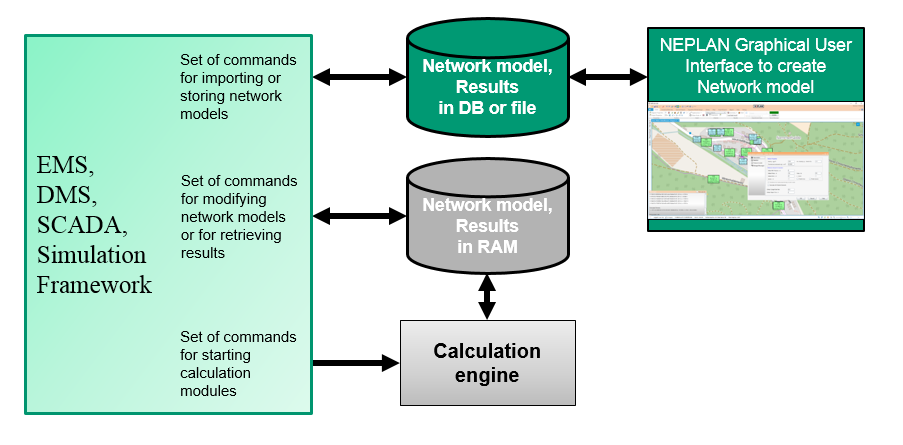
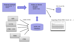
NEPLAN | Web Services / Scripting / OEM Integration
back to overview
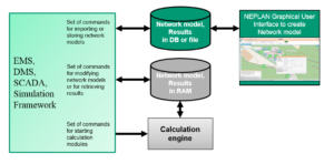
NEPLAN has different possibilities to define automated processes in regard to simulation, updating the network model and importing real time measurements, creation of user-defined calculation functions, interfacing with external systems, etc.
Web Services
The NEPLAN web service for C# allows editing all network model parameters, running all network calculation and retrieving the calculation results as well as calling all import/export functionality. Applications using NEPLAN web services are communicating with NEPLAN, which could be hosted on a desktop, in an Intranet or Internet environment. The web services allows to develop Apps to access network and measurements data as well as information about protection devices in the field. The high level programming language Python is supported by the NEPLAN web services. This is often used to create batch processing.
OEM Integration
NEPLAN offers an API library (DLL-Library) to integrate the complete set of NEPLAN functionality into external system, such as Geographical Information Systems, SCADA, DMS or Smart Grid application. An external application, which uses the NEPLAN API, runs completely independent on the installed solution of NEPLAN.
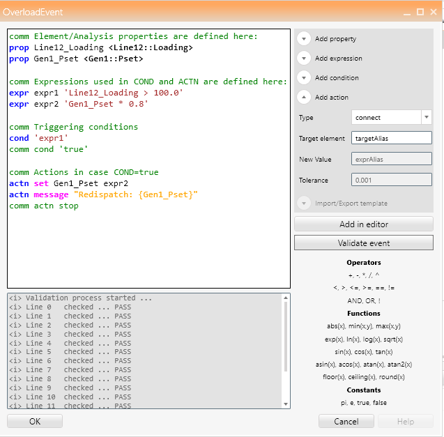
Event Editor for Remedial Actions
The scripting language within NEPLAN allows to create custom events during a calculation process. In this way remedial actions could be easily defined. Every state of the simulated network can be monitored and, if necessary, adjusted, e.g. dispatch of generated power in case of overload or adjust the transformer tap in case of voltage violations.

NEPLAN | Graphical User Interface
back to overview
Drawing a network
- Different types of lines, cables and pipes can be drawn freely with the mouse on the graphics panel and can have any arbitrary form
- Electrical, gas, water and heating elements can be selected from a tool box
- Many elements are available in several different representations
- Inserting an element a dialogue pops up, where all specific physical parameters can be defined
- The drawn network can be copied and pasted via OLE into MS-Word or other applications
- The physical parameters associated to an element can be copied all at once to another element
Auxiliary graphics
- Auxiliary graphics can be used for documenting the diagram
- It is possible to draw lines, rectangles, ellipses, arcs, ellipse sections, polygons, polylines, any kind of bitmap graphics
- Texts with selectable character sets can be drawn into the diagrams
- The colours for background, foreground, line, outlines and fill patterns are user-selectable
- Functions are available for rendering overlapped symbol elements, alignment and rotation
Colouring of network
- Colours and line types can be freely selected
- Elements overloaded after a load flow or short-circuit-current analysis are colour-highlighted
- Isolated elements can be highlighted
- Colouring options to distinguish user-defined network areas, zones, feeders, voltage levels, earthed or un-supplied networks and galvanic separated networks
- Differences to the parent variant or the root net can be coloured
- Each element can be coloured individually
- User defined graphic layers can be coloured
- Colouring according to ranges. Many calculated variables can be coloured according to their values (e.g. according to element losses or according to voltage drops)
- Colours of results in tables and graphic charts, flow animation, background visualization, gauche, pie charts can be freely selected
Symbol editor
- The user can create and define for each element type and node its own symbols
- User defined Symbol Libraries
- It is possible to define more than one representation for each element type
- All symbols will be displayed when entering the diagram. The desired symbol can be dragged and dropped into the graphics panel
- On the graphics panel the symbols can be flipped, rotated and resized
- Delete. copy, move, insert, zoom and align are also functions available for symbol editing
Visualisation of networks in separate diagrams and layers
- The visualisation of a network can be separated into several diagrams. In this way it is for example possible to show the low voltage part in one diagram and the medium voltage part in another
- The content of a diagram can again be divided into several layers. This allows to hide or colour the content by layer
- Zooming into stations: in one diagram an overview of all the network can be shown with the station shown as a simple box, in other diagrams the details of each single station with all its breakers, protective devices and instruments
- Topological the elements can be linked between several diagrams
- All diagrams will be considered for various analyses (e.g. load flow)
- An element can have more than one graphical representation in the same diagram or in different diagrams
- Graphical data can be imported in MS-Word or other programs with Copy/Paste (OLE)
Chart manager
- The chart manager allows to display the results in different charts. (e.g. line, bar, etc.)
- Any number of sub charts can be displayed in one chart
- A user defined logo (as bitmap) can be added to the header for documentation purposes
- Results from different variants can be compared and displayed in the same chart
- The chart can be exported as an image
- Copy/paste to the clipboard is possible for documentation purposes. (e.g. to MS-Word)
Multi-lingual graphical user interface
The user interface of the software is available in English, German, French and other languages.
Videos:
- Introductory video to Graphical User Interface (Tutorial) could be found here.
NEPLAN | Data and Study Case Handling
back to overview
NEPLAN offers the most intuitive Data Manager, with a multi-document, multi-window, table oriented system where all data can be entered for example as an Excel sheet. NEPLAN makes data handing easier as ever, as it provides interfaces to external programs and data and graphic can be exchanged with third party software (OLE-functionality).
General Characteristics
- The equipment data are entered in dialogues, with plausibility checks. A colouring tool helps to show which data is needed for which analysis (e.g. short circuit, transient stability etc.)
- Integrated Variant Manager (insert, delete, append, compare variants, compare results, etc.)
- ASCII file or SQL database oriented import/export functions for exchanging network data, topology data and load data are available
- Option for combining and separating networks. Any number of independent network areas and zones are possible. Each element and node can belong to any independent area and zone
- Extensive functions for network statistics and network documentations are available
- A state of the art library manager with extensive libraries for each element type facilitates data entry
- All computation modules access a shared database
- Integrated chart manager allows to analyse and compare all results from all variants
- Multi-lingual function
Operational data
- Start time of operation could be assigned to each component
- Outage time for operation could be assigned to each component
- Information about projected component or component in maintenance
- Time dependent network state for calculation
Variant (study case) Management
- Non-redundant storage and management of variants
- For each network user may select: any desired switch states and any desired loading states
- For each network user may define and store any desired number of variants and subvariants (variant tree). In the variant data, only the differences from the parent variant are saved
- Variants can be compared, merged and deleted
- The diagrams of different projects and variants can be displayed at the same time
- Results from two different variants can be displayed on the diagram in one result label
- Results of two variants can be compared in the chart manager
NEPLAN | Network Modelling
back to overview
NEPLAN is handling any type of electrical networks for transmission, distribution and industrial/generation.
Network types:
- Meshed or radial 1-phase, 2-phase, 3-phase with separate representation of neutral and/or ground
- Meshed or radial DC systems
- Combination of AC and DC networks with AC/DC and/or DC/AC converter
- Grounded, impedance grounded, resonance-grounded and isolated
Voltage levels:
- Ultra-high voltage to low voltage
- All voltage levels are handled in one calculation run
Grouping of network components
- Area/subarea, zones/subzones, feeder, substation, element groups
- Partial networks, isolated networks, grounded networks
- Owner
- Tie-lines or -components
Passive network components
- Overhead lines with tower geometry and calculated mutual coupling
- Any cable with parameter calculation
- 2-, 3- and 4- winding and autotransformer
- Special asymmetrical transformers (single, two-phase or three-phase configuration)State-of-the art Phase shifting transformers (4-quadrant)
- State-of-the art on-load tapchanger with asymmetrical voltage step and impedance correction
- Voltage regulator and thyristor-based regulator (single, two-phase or three-phase configuration)
- Filters and RLC components
- Earthing transformers and earthing systems for common earthing of components
- User-defined models
Switches
- Load switch, disconnect switch, busbar coupler (single phase, 3-phase configurations)
- LV-, MV-, HV-circuit breaker (single phase, 3-phase configurations)
- Grounding switch and surge arrester
- Remote controlled switches
- Automatic reduction of switches during calculation
Substations
- Any substation configuration with/without bay definition
- User defined switch bay configuration
- Supports hierarchical structure
- Substation templates could be used
- Definition of grounding system
Renewables and Energy storage
- Small and large hydro power plant
- Small and large wind power with detail representation
- Photovoltaic
- Biogas
- Fly wheel for AC/DC machines
- Compressed air storage
DC-components
- HVDC classic with DC-lines (2-port or 3-port configuration)
- Voltage source converter, HVDC-light (2-port or 3-port configuration) and PWM
- DC-reactor and DC-shunt
- DC-batteries, DC-Fuel cells and DC voltage source
- DC photovoltaic panel
- DC-motor and DC-load
Compensation components
- Line compensation
- Block-wise shunt compensation in fix, discrete or continuous control mode
- Static Var compensation and STATCOM
- Series-compensation with over voltage protection
Generators
- Synchronous machines with state-of-the-art models for steady state and dynamic behaviour for nuclear power
plant, hydro power plant, gas power plant, combined cycle power plant, coal-fired power plant
- Direct drive synchronous machine with permanent magnet
- Double fed asynchronous machines as one port or two port model
- Disperse generation
- External Grid (voltage source)
- User-defined models
Motors
- Asynchronous machines with all kind of start-up devices
- Synchronous with all kind of start-up devices
- Automatic motor parameter identification out of input values in function of slip
- Converter fed drive
- User-defined models
Loads
- Motor, constant current and constant power load or mixed
- Composite load for LV-consumers
- LV-loads assigned to lines, e.g. cables
- Frequency dependent loads for HV
- synthetic load profiles (day, season) and measurements
- load forecast
Controllers
- Generators, motors, transformers, compensation, HVDC, VSC or any other component could be controlled. e.g.
Automatic Voltage regulators, Turbines, Governors, PSS
- Secondary control for frequency or balancing control
- Controllers are built with help of function blocks or simulation language (MatLab)
- Pre-defined controllers are available
Protection
- Over current relay with i/t characteristic, supports all standards IEC, BS, ANSI/IEEE
- LV- and MV-circuit breaker, fuses, recloser
- More than 3500 protection models available
- Distance protection with any R/X-characteristic
- Voltage, frequency and power swing relay
- Pole slip relay
- Differential relay
- User-defined modelling of any protection device with function blocks