NEPLAN | Optimal Separation Points
back to overview
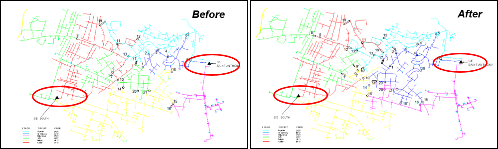
For networks which are structured as meshed but are required to be operated radially, the determining of the radial configuration is needed. The module Optimal Separation Points (Switching Optimization) calculates the optimal radial configuration through the available sectionalizing switches. The optimization process can take into consideration several objective functions such as minimizing power losses and users can apply various constraints such as treating certain switches as non-switchable. The results contain the optimal switching configuration, and the benefits achieved compared to the initial configuration and can be automatically applied to existing models.
NEPLAN | Small Signal Stability
back to overview
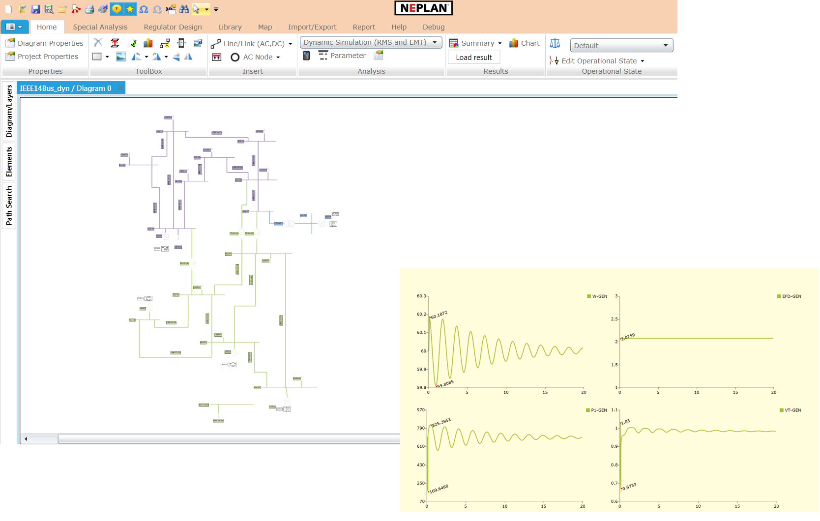
The NEPLAN Small Signal Stability module offers eigenvalue analysis (modal analysis) for electrical power systems. It provides information about the inherent dynamic characteristics of the power system and assists in its design. It is typically used in studies of interarea oscillations. It combines exceptional ease of use with the latest techniques and standards in both electrical power engineering and software design.
General Characteristics
- Data scanning and eigenvalue sensitivity functions
- Automatic construction of the linearized state space notation for the complete system, including generators, static loads, control circuits, etc.
- Advanced synchronous machine modelling. Selection for every synchronous machine of one of the five models: infinite, classical, transient, subtransient and general. Saturation curves for both, d-axis and q-axis
- Automatic calculation of eigenvalues, eigenvectors, mode shapes, participation factors for eigenvalues and state variables
- Text results: results are presented in clear form and can be customized by several output options
- Graphical results: results can be visualized by the fully integrated graphical results manager. Charts can be easily printed and exported to external programs (e.g. Microsoft Word) by clipboard functions. A variety of chart options is available
- The only requirement is the NEPLAN Load Flow module. However, the Small Signal Stability and the Transient Stability (Dynamic Simulation) module of NEPLAN complement each other ideally
- The Small Signal Stability module is completely integrated in NEPLAN and uses standard dynamic element data.
Applications
- Analysis of interarea oscillations
- Analysis of interplant oscillations
- Analysis of subsynchronous oscillations/resonance (SSR)
- Identification of groups and subgroups of machines swinging against each other
- Determination and improvement of power oscillation damping
- Design and placement of control equipment, such as Power System Stabilizers (PSS)
- PSS tuning
NEPLAN | Electromagnetic Transient (EMT)
back to overview
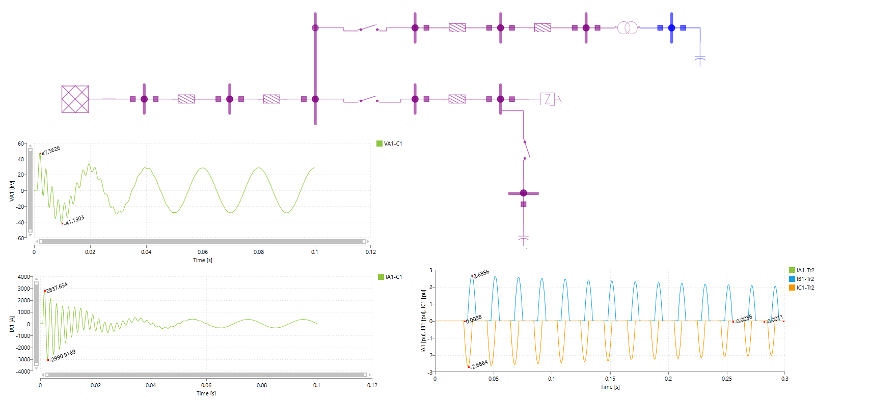
The EMT simulation module requires the RMS simulation module and allows to perform electromagnetic transient simulation in ABC reference frame (multi-phase system), where the electrical model quantities are described by their instantaneous values. The module implements a unique mathematical framework for large-scale, nonlinear system with fast/slow continuous and discrete (hybrid) events. The initialization of the mathematical model is performed by high sophisticated algorithms in an automatic way and is fully integrated. The time-consuming model-specific initialization process could be omitted. The NEPLAN Simulation Language (NSL-SymDef) is used to define models, but an extensive built-In library is also available.
The module has the similar characteristics in respect of modelling and co-simulation as the RMS stability analysis, supports COMTRADE-files and has Frequency analysis Tool with Fast Fourier Transform (FFT). The module is used, but not limited to
- Transient over voltages
– Load rejection
– Ground fault
- Transient Switching over voltages (e.g. line energization)
- Transformer/capacitor/filter-energization (inrush current)
- Ferro-resonance
- Sub-synchronous resonance
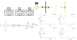
NEPLAN | Stability Analysis (RMS)
back to overview
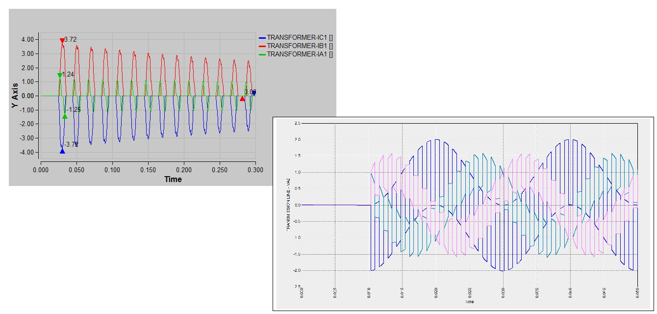
The module RMS Stability Analysis is one of the most advanced tool for dynamic simulations on the market and allows to simulate symmetrical and unsymmetrical networks and events. It implements a unique mathematical framework for large-scale, nonlinear system with fast/slow continuous and discrete (hybrid) events. The initialization of the mathematical model is performed by high sophisticated algorithms in an automatic way and is fully integrated. The time-consuming model-specific initialization process could be omitted. The NEPLAN Simulation Language (NSL-SymDef) is used for user-defined models, but an extensive built-In library for e.g. Wind turbines (IEC 61400-27-1 standards), Photovoltaic (CIRED standard) and CIM ENTSO-E models is also available.
Main characteristics:
- Short-term, mid-term and long-term dynamic simulations
- Symmetrical and asymmetrical AC and DC networks (same as for steady state calculation)
- Simulation of symmetrical conditions and events in DQ0 reference frame for higher performance
- Simulation of unsymmetrical conditions and events in ABC reference frame (multi-phase system)
- High accuracy and performance (simulation in real-time) with fixed and variable step-size algorithm
- Simulation of any fault or event, see examples below
- Behavior of protection devices in pre-defined library are considered during simulation, see examples below
- User defined protection models described by equations or function blocks
- Transient Motor starting for synchronous and asynchronous machines with start-up devices
- Model definition through NEPLAN Simulation Language and compiling to Dynamic Link Library (DLL)
- Graphical editor for creating models (AVR, relay, etc.) through function blocks and automatic compilation to Dynamic Link Library (DLL)
- Open framework to monitor and control any variable in the network system
- Co-simulation with external systems
- Frequency Analysis with Fast Fourier Transform (FFT)
Typical applications
- Grid Interconnection Studies for Renewable Energy and verification of grid code compliance
- Machine dynamics and startup simulations
- Rotor angle stability with several different type of regulators
- HVDC-(light), FACTS, SVC design and regulation
- Load shedding and protection schemes
- Automatic generation control (AGC)
- PSS tuning with Eigenvalue and Sensitivity analysis
- Wide area network controllers
Typical protection models
- Min-max relays (e.g. over current, under voltage, power and frequency): modeled with the possibility to trigger of any desired event (e.g. switching in/off an element, increase/decrease load, loss of excitation). Various load shedding schemes can be easily simulated
- Overcurrent relays, circuit breakers and fuses
- Pole slip relays, including binary input signals from external sources
- Out-of-step protection including Power Swing Blocking (PSB) and Out of Step Tripping (OSP)
- Distance protection with any characteristic: pickup and tripping stages, impedance diagrams, binary input signals from external sources
Typical disturbances (events)
- Possibility of defining and saving various disturbance groups, with different single event per case
- Definition of different faults (symmetrical and unsymmetrical) on buses, bus elements, branches
- Different switching operations (feed-forward control in control circuits, cross coupling of protective devices, in/out of branches, etc.)
- Loss of generator excitation
- Start-up of motors with different start-up devices
- Transformer tap modification
- Load shedding scenarios (even in relation with frequency relay)
- Disturbances with function activation (step, ramp, sinusoidal function or combination)
- User-defined disturbances (every variable can be modified in the network/control)
- Definition of specific voltage profile on buses for Low Voltage Ride Through (LVRT) and Over Voltage Ride Through (OVRT)
Brochure: Introductory brochure for stability analysis could be found here.
Videos:
- Introductory video to Dynamic (Stability) analysis could be found here.
- Learning video for modelling controllers for Stability analysis with NSL-SymDef could be found here.

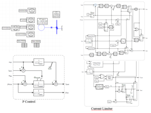
NEPLAN | Modelling
back to overview
NEPLAN offers for dynamic analysis an extensive and detailed set of models for all the power system elements, renewable energy sources, storage systems and power electronics. An extensive library of controllers for e.g. exciters, turbines, PSS, Wind turbines (IEC 61400-27-1 standards) and Photovoltaic (CIRED standard) are available. A subset of available controllers is shown here.
The modules can handle AC and DC networks, including HVDC systems, DC-lines and several DC elements (batteries, photovoltaic panels, fuel cells) at the same time in one common system. All the models are described in the Differential Switched-Algebraic State Reset Equations structure, called DSAR.
The user-defined models could be created by
- the NEPLAN Simulation Language (NSL-SymDef)
- the Graphical Editor with Function blocks
The created models will be automatically compiled to a Dynamic Link Library (dll), which will be used during the simulation. The flexible simulation Framework allows to monitor and control any variable in the network.
Video: Learning video for modelling with NSL-SymDef could be found here
NEPLAN | Advanced Features
back to overview
In NEPLAN there are two explicit modules to handle protection devices, these are
- Over current protection and
- Distance protection
All other protection devices could be defined in NEPLAN and the corresponding calculation or simulation module uses the particular device to perform its duties. Especially the module Dynamic Analysis is able to model any protection device and show its behaviour during an event in the network.
Frequency relays (used for dynamic analysis)
- Monitored variable is the frequency or its derivative
- Up to four tripping stages could be defined
- Event definition for each stage (e.g. disconnect of loads)
- Circuit breaker delay time
Maximum relay nodes (used for dynamic analysis)
- Monitored variable is voltage and voltage angle or their derivatives (voltage relay)
- Up to four tripping stages could be defined
- Event definition for each stage (e.g. disconnect of loads, generator)
- Circuit breaker delay time
Minimum relay nodes (used for dynamic analysis)
- Monitored variable is voltage and voltage angle or their derivatives (voltage relay)
- Up to four tripping stages could be defined
- Event definition for each stage (e.g. disconnect of loads, generator)
- Circuit breaker delay time
Maximum relay elements (used for dynamic analysis)
- Monitored variable is current and current angle, active and reactive power, impedance magnitude and angle, resistance and reactance or their derivatives (power relay)
- Up to four tripping stages could be defined
- Event definition for each stage (e.g. disconnect of loads, generator)
- Circuit breaker delay time
Minimum relay elements (used for dynamic analysis)
- Monitored variable is current and current angle, active and reactive power, impedance magnitude and angle, resistance and reactance or their derivatives (power relay)
- Up to four tripping stages could be defined
- Event definition for each stage (e.g. disconnect of loads, generator)
- Circuit breaker delay time
Pole slip relay (used for dynamic analysis)
- Out-of-step protection for generators
- Monitored value is the apparent impedance seen by the generator terminals
Differential protection (used for reliability analysis)
- Monitored value is the sum of incoming and outgoing currents (busbars, transformers, etc.)
Advanced modelling for dynamic analysis
- Exact relay behaviour could be modelled with function blocks
- Monitored values for phase voltages and currents after a disturbance are input values to the relay model
- More than 30 function block types are available, e.g. summation, if-then-else, pickup delay, reset delay, polygon, time dependent delay

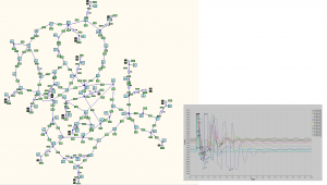
NEPLAN | Fault Finding
back to overview
This module allows the detection of faults in electrical networks. Fault Finding addresses essentially faults in normal networks and in resonance earthed networks (the measured distance related to the total ring length or the total ring reactance).
General Characteristics
- Detection of fault location or faulted elements based on measured phase currents, phase voltages or reactances
- Measured values are entered in the protection devices or imported
- Detection of all nodes in a certain range of tolerance defined by the user
- Calculation is independent of the network structure and voltage level for short circuit
Results
After the calculation, the module will display the following results:
- Faulted element . It will also be displayed on the single line diagram
- Fault distance
- Nodes between which the fault was located
- Nodes within the faulted area defined by the range of the tolerance
NEPLAN | Distance Protection
back to overview
The Distance Protection module allows the user to enter distance protection relays with their settings or characteristics, get all voltage, current, and impedance values (primary or secondary) seen by a relay due to a short circuit, check the relay settings, set the relay automatically or manually, enter the tripping schedules, and activate a fault clearing procedure. All types of distance protection relays (irrespective of the manufacturer) can be entered. All fault types, plus sliding faults of the short circuit module are allowed.
General Characteristics
- Relays up to 4 impedance zones, 1 over reach zone, 1 backward zone, 1 power swing zone and 1 auto-reclosure zone for line-line and line-earth faults can be defined
- Start-up characteristics: over current, angle dependent under impedance, R/X-characteristic, directional/bi-directional and time
- Input of any R/X-Characteristic: MHO, Circle, Polygone, Lens, or defined point-by-point
- Simulation of fault clearing procedure in meshed networks based on the short circuit module. It involves also over current protection
- Automatic setting of the relays considering several methodologies (selectable)
- Mutual impedances and capacitances of the positive and zero sequence systems as well as the loading state of the network and infeeds are considered for calculating network impedances
- Impedance/Reactance of the positive sequence system or the loop impedances are calculated for any short circuit type. Compensation factors due to zero sequence system impedance and mutual coupling are considered in calculating the loop impedances
- Automatic and user-defined creation of selective tripping schedule
- Interactive change of relay setting parameters and characteristics
- Impedances can be entered/displayed in primary or secondary values. CT and VT are considered
- Processes analog and binary signals and sends out binary signals during dynamic simulation. Binary signals can be: Blocking, Enable, Intertripping, Range Extension, External Starting, Auto-reclosure Blocking, etc, e.g. POTT (Permissive over-reach transfer tripping) and PUTT (Permissive under-reach transfer tripping) can be simulated.
- Interaction between distance protection relay with any other relay type can be defined for dynamic simulation
- Relay can be modelled within Matlab/Simulink or with NEPLAN® function blocks for dynamic simulation
- Interface to relay test devices. Import/Export of RIO-Format (Relay Interface by Omicron)
Results
- Tripping time will be displayed in the single line diagram and in tables after a short circuit calculation
- Display of all calculated impedances with the relay characteristics
- Multiple short-circuits and tripping schedule can be displayed on charts
- All calculated values can be exported in an Excel-based format
- Fault location finding. Fault location will be displayed in the single line diagram or listed according to the previously measured impedance value. Tolerance will be considered
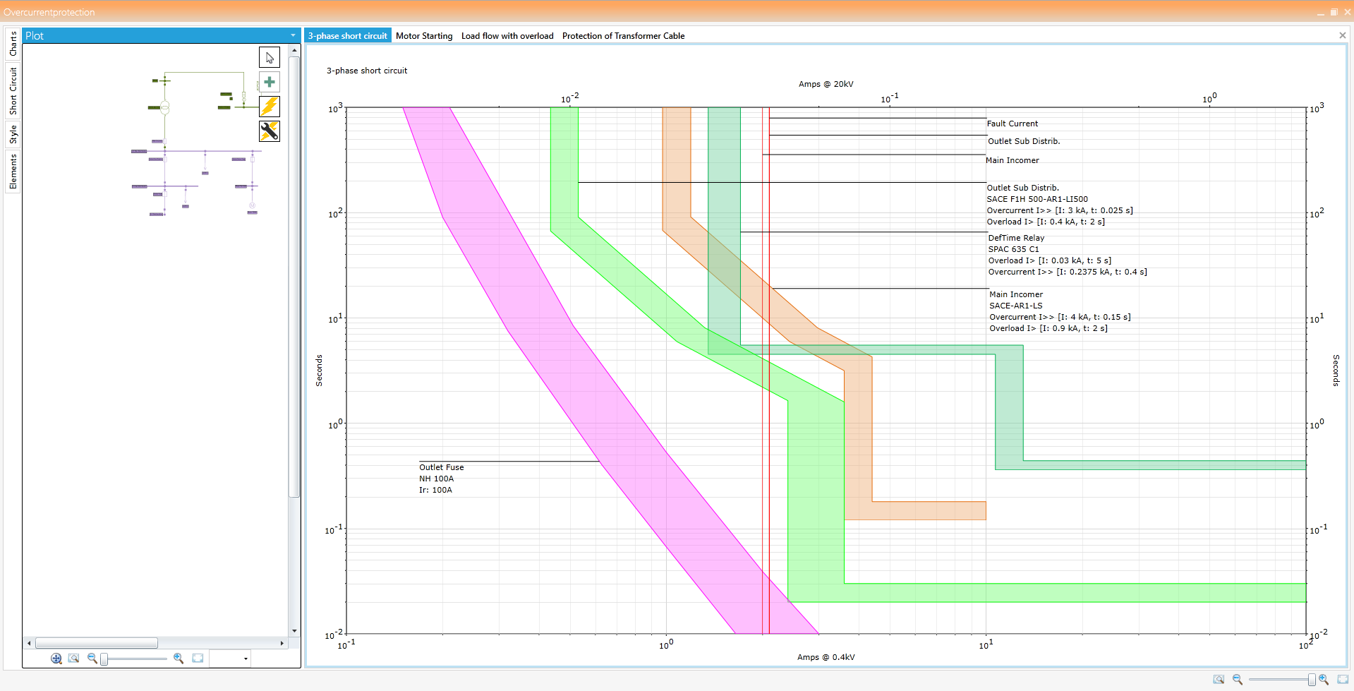
NEPLAN | Overcurrent Protection (Selectivity Analysis)
back to overview
This module is used for the coordination of various over-current protection devices in a given network. The response of the over-current protection devices is visualized in the Time-Current Characteristic (TCC) curve. These TCC curves can be viewed on the selectivity diagram using which the user can adjust the settings of these devices to protect the cable, transformer, etc.
General Characteristics
- All types of protective devices with a current-time characteristic can be entered: fuses, circuit breakers, definite-time and inverse-time over-current relays, electronic relays
- Several protective functions can be assigned to each protective device: non-directional or directional (over-current and earth-fault protection)
- Exact modelling of setting ranges
- Extensive libraries with protective devices from a variety of manufacturers are available and can be extended at will
- Option for entering user-defined characteristics for simulating motor start-ups or thermal capability of cables, damage curves of transformers, etc.
- Characteristic can be shifted using a k-factor (inverse-time relay)
- Entry options for characteristics: point-by-point or formula in conformity with IEC or IEEE/ANSI
- Simulation of fault clearing procedure in meshed networks, involves also distance protection
Selectivity Diagram
- Protection device and current transformers are positioned in the network plan graphically
- Single-line diagram can be viewed in the selectivity diagram
- Automatic generation of selectivity diagrams based on s/c calculation
- Unrestricted number of characteristics can be incorporated in one diagram
- Changing the relay settings directly in the selectivity diagram by moving the curves with mouse or with the help of navigation arrows
- Unrestricted number of diagrams can be processed simultaneously
- Selectivity analysis over more than one voltage level and independently of the network type and size involved
- Two reference voltages for diagrams can be defined by the user
- Individualized colouring of the characteristics
- No limit on number of diagrams and protective numbers for management
- Export of complete diagram to PDF, Word, PNG etc.
- Possible to print the charts from the selectivity diagram
- Axis settings and fonts for the labels can be changed in the diagram
- Short circuit calculation can be done directly from the selectivity diagrams
Transferring Current Values
- Short circuit currents as well as other currents can be incorporated in the selectivity diagram
- Unrestricted number of currents can be transferred into one diagram
Protection Libraries
NEPLAN offers extensive libraries with most used relays-, circuit breaker – and fuse-types. The libraries are constantly updated and extended. They will be handed out for free at the moment of a NEPLAN software purchase or can be downloaded any time from the Internet by users with a valid maintenance contract.
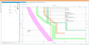
Selectivity Charts
NEPLAN | Economic Cable Sizing and Thermal Analysis
back to overview
This calculation module checks all cables and overhead lines on their thermal capacity. Control is independent of the network structure (meshed, radial) and it requires the protection devices’ characteristics. The tripping time of protection devices is also considered. The calculation can be performed according to:
- DIN VDE 0100 Part 540
- DIN VDE 0103 or IEC 865-1:1993
- ANSI
Results
- Worst fault location for thermal cable stress
- Permissible thermal cable current according to standards and line input values
- Permissible fault clearing time calculated
In case no protection devices are entered, the module can still calculate the maximum allowable fault clearing time.