The Optimal Power Flow (OPF) function serves to determine the most efficient operating conditions for an electric power network under specified constraints. It computes optimal generator dispatch levels and bus voltage setpoints that minimize predefined objectives such as generation costs or active power transmission losses. The optimization process is subject to engineering and system limits, including AC power flow equations, generation capacity bounds, acceptable bus voltage ranges, thermal ratings of transmission lines, and inter-area power exchange constraints. In operational contexts, OPF assists system operators in maintaining reliability while economically optimizing power flow. It enables the simulation and enforcement of equipment limits, supports voltage profile adjustments, and contributes to secure dispatch decisions. The solution of all OPF problem is typically achieved via the aid of nonlinear optimization techniques, in particular primal-dual interior-point methods.
Algorithms
The Optimal Power Flow (OPF) module is designed as a highly flexible framework that adapts to a wide range of operational needs. Rather than offering rigid submodules, NEPLAN allows users to configure the OPF environment by selecting control variables, constraints, and objective functions that suit their specific goals. Functionalities such as reactive power optimization and economic dispatch are seamlessly integrated and can be customized within a unified interface. All OPF algorithms adopt AC power flow modelling.
For example, Reactive Power Optimization can be achieved by keeping active power generation fixed to predefined values, as indicated by the user or derived from scheduled dispatch plans. The OPF then adjusts reactive sources—such as generator voltage setpoints, transformer tap changers, and compensation devices—to optimize voltage profiles and maintain adequate reactive reserves across the network. Economic Dispatch Optimization on the contrary requires cost-based control of active power generation, ensuring efficient utilization of resources while respecting system constraints.
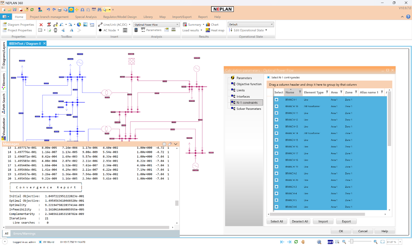
The Security-Constrained Optimal Power Flow (SC-OPF) module extends the capabilities of OPF by incorporating N-1 contingency analysis directly into the optimization process. It ensures that the computed operating point remains secure even under predefined failure scenarios, such as the outage of a transmission line, transformer or generator. This module is particularly valuable for transmission system operators seeking to enhance reliability without compromising economic efficiency.
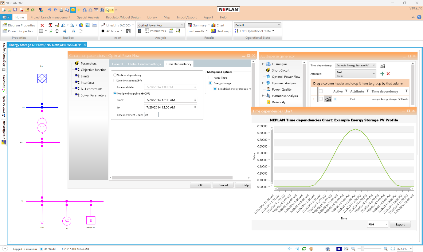
The Multiperiod Optimal Power Flow (MOPF) module in NEPLAN extends traditional OPF analysis by incorporating time-coupled constraints across multiple time intervals. This allows users to simulate and optimize network operation over a defined planning horizon—ranging from minutes to days—while accounting for dynamic system behavior. MOPF supports the modelling of energy storage systems, including battery charge/discharge cycles, state-of-charge limits, and injection/extraction efficiencies. It also integrates generation ramping constraints, enabling realistic scheduling of conventional units with limited flexibility. These features are essential for renewable integration, and system balancing under variable conditions.
All OPF modules integrate seamlessly with the graphical interface, allowing users to visualize optimization results directly on the single-line diagram. Voltage violations, overloaded elements, and binding constraints are clearly highlighted, supporting informed and efficient decision-making.
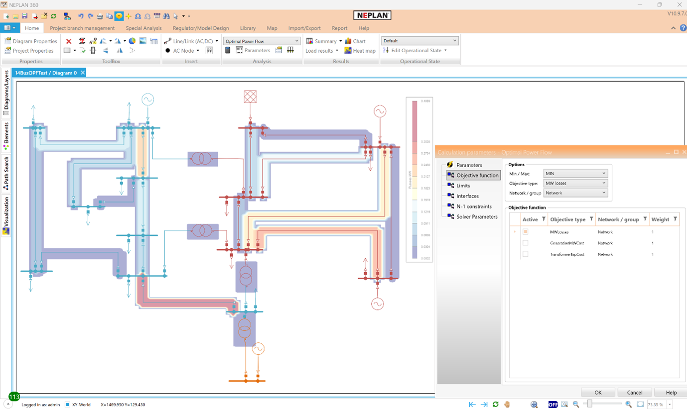
Objectives
• Minimisation of losses
• Minimisation of costs (active/reactive)
• Minimisation of costs (shunts, transformer taps)
• Minimisation of active costs (Static Var Systems)
• Minimisation of power import
• Minimisation of boundary flows
• Minimisation of transformer flows
Control variables
• Generator active/reactive powers
• Transformer and shunt taps
• Static Var Systems
• HVDCs
Constraints
• Generator active/reactive power limits
• Branch flow limits
• Bus voltage magnitude limits
• Boundary flow limits
• Storage devices capacity limits (MOPF)
• Generator ramping (MOPF)
N-1 Contingency constraints (AC only)
• Transmission lines
• Transformers
• Generators
• Shunts
• Loads
• Static Var Systems
Results
There are several possibilities to view and analyse the results of each calculation. Similarly to load flow calculations:
• Violated elements/nodes are highlighted.
• Table results can be sorted and filtered.
• Many visualization options available (line thickness, heatmaps, charts etc.)
• Raw results can be exported in different formats.